
How fluid control systems dispensing improves dosing consistency
by
Published
Views:
When an adhesive bead begins to vary from part to part, the visible defect is often only the last symptom. A bond line may look wider on one assembly, a potting cavity may be underfilled on the next, or a sealed housing may show intermittent squeeze-out. In automated production, these variations can create downstream problems in cure quality, electrical protection, mechanical strength, cleanliness, and material consumption.
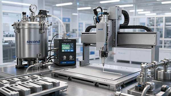
Fluid control systems dispensing improves dosing consistency by controlling the conditions that determine delivered volume at every cycle: material pressure, flow path resistance, valve opening time, shot profile, nozzle condition, and the relationship between the dispenser and the workpiece. The purpose is not simply to move fluid from a reservoir to a part. It is to deliver the intended amount despite changes in viscosity, temperature, pressure loss, and production speed.
Why a stable pump setting is not enough
A dispensing program can remain unchanged while actual output drifts. This is especially common with filled epoxies, moisture-sensitive polyurethanes, thermally conductive silicones, UV-curing adhesives, and materials that change rheology during use. A fixed pressure setting may produce an acceptable bead at the start of a shift but a different volume after the material has warmed, settled, entrained air, or traveled through a partially restricted nozzle.
The same issue appears in low-volume applications. On a camera module, sensor package, or fine-pitch electronic assembly, a small variation in deposited volume can affect component seating, fillet geometry, capillary flow, or cure exposure. On a larger EV battery or industrial enclosure, variation can leave voids in a sealing path or cause excessive overflow that must be removed before the next assembly stage.
Dispensing consistency therefore depends on controlling a process, not merely selecting a nominal flow rate. A capable fluid control setup coordinates material conditioning, supply pressure, metering behavior, valve actuation, motion, and verification. Each element influences the next.
Delivered volume is shaped by more than valve-open time
In simple timed dispensing, a controller opens a valve for a programmed duration. This can be effective for stable, low-viscosity materials under tightly controlled conditions. However, time alone does not guarantee volume. The amount delivered during that interval depends on the pressure differential across the valve and the resistance of the complete flow path.
Resistance changes with hose length, inner diameter, filter condition, nozzle geometry, material viscosity, and cured residue near the outlet. A narrow needle may offer the placement accuracy required for a fine bead, yet it also becomes more sensitive to viscosity variation and partial blockage. With abrasive or heavily filled compounds, nozzle wear can gradually enlarge the flow opening and change the deposit profile even when all programmed values appear correct.
Fluid control systems dispensing addresses these effects by using methods such as closed-loop pressure regulation, positive-displacement metering, controlled valve strokes, suck-back, and repeatable actuation signals. The correct method depends on the material and application. A system should be assessed by how well it maintains a required deposition window, not by its maximum advertised output.
The first engineering question: what must remain consistent?
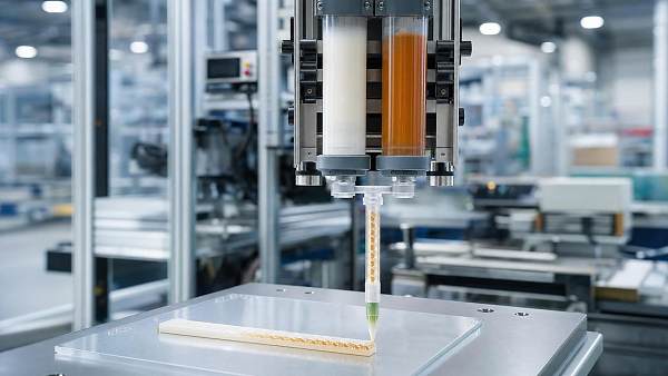
“Consistent dispensing” can mean different things. Before comparing equipment, define the actual controlled output. For a sealing bead, the relevant measure may be continuous bead cross-section and positional accuracy. For a dot application, it may be mass, volume, diameter after wetting, or deposited height. For a two-part epoxy, the requirement may include mix ratio, total dose, and the absence of unmixed material.
This distinction prevents a frequent evaluation error: validating a process only by visual appearance. A bead can look continuous yet contain flow variation that changes its final thickness. A round-looking dot can have an acceptable diameter but excessive height because the substrate surface energy or stand-off distance has changed. Weight-based checks, vision inspection, profilometry, or process pressure trends may each be useful, but the inspection method should match the functional requirement.
Define the acceptable range before selecting controls. The range should account for the functional effect of underfill or overfill, not only the smallest variation that an instrument can detect. Once this range is known, the dispensing system can be evaluated against realistic material and production conditions.
Choose the metering principle around material behavior
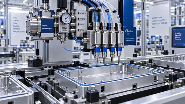
Pressure-time dispensing is practical where shot tolerances are moderate, the material is stable, and frequent calibration is acceptable. It is often used for low-volume fluid application, but its repeatability is strongly linked to pressure stability and rheology. It may be less suitable where the material changes significantly over a production period or where very small deposits have a narrow allowable range.
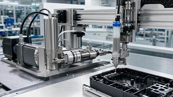
Positive-displacement systems meter a defined mechanical volume through a piston, screw, gear, progressive cavity element, or similar mechanism. They can reduce dependence on upstream pressure and are often considered for more demanding dosing work. Their suitability still depends on the fluid. High-viscosity, shear-sensitive, abrasive, filled, or reactive materials require attention to internal wear, dead volume, cleaning access, and shear exposure.
Jetting systems are useful when contact dispensing is too slow or risks disturbing the substrate. A piezoelectric jet valve can place small deposits at high speed with a controlled stand-off distance. Yet jetting does not eliminate process control requirements. Material viscosity, particle size, nozzle and tappet condition, drive settings, and fluid temperature remain critical. A jet process should be qualified using the actual adhesive or encapsulant, not a lower-viscosity substitute used only for initial demonstrations.
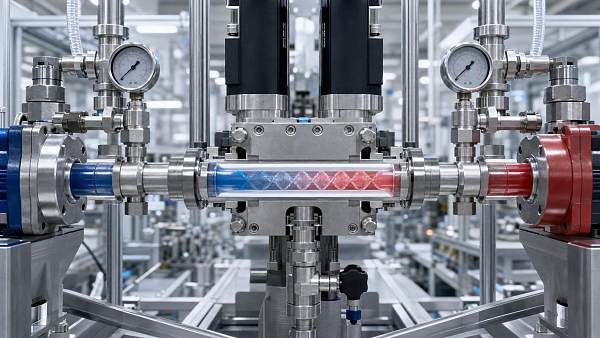
For two-component materials, ratio control introduces another layer of risk. A stable total output does not prove that the mix is correct. The A and B streams must remain proportioned through the selected operating range, and static mixer design, material residence time, and flushing practice must be considered. A mixer can create pressure drop that changes as material begins to react, so monitoring only the pump command may not reveal the entire problem.
Where dosing variation usually enters the process
When variation occurs, replacing the valve first can be an expensive distraction. A more useful approach is to trace the fluid path from bulk supply to the deposited pattern. Start with the condition of the incoming material. Was it stored and conditioned within its supplier-defined limits? Has a filled formulation been mixed or recirculated as required? Has it been exposed to moisture, temperature cycling, or a hold time that could alter viscosity or cure behavior?
Next, inspect the supply system. Emptying drums, collapsing liners, inconsistent follower-plate sealing, or an unstable feed pump can introduce pressure fluctuations. In cartridge processes, air pockets can enter during loading or manual transfer. These pockets compress and expand, producing delayed starts, sudden spurts, and erratic dot volume. The symptom may be mistaken for an electrical valve fault even though the cause sits upstream.
The hose and valve assembly should then be examined as a single flow section. Long hoses increase material lag and pressure loss. Unsupported hoses can move with robot travel, affecting their stress state and sometimes the response at the valve. Heating zones should be checked for actual, uniform temperature rather than relying only on setpoints. For reactive materials, poorly controlled temperature may change both viscosity and usable working life.
At the outlet, inspect the nozzle, needle, or jetting interface. Cured buildup changes geometry. A damaged tip can create asymmetric flow and shift bead placement. The distance between the outlet and the substrate influences how a bead lands and spreads; a process can appear to have a volume problem when the true issue is changing stand-off caused by fixture tolerance or part warp.
Motion control can either preserve or distort a stable dose
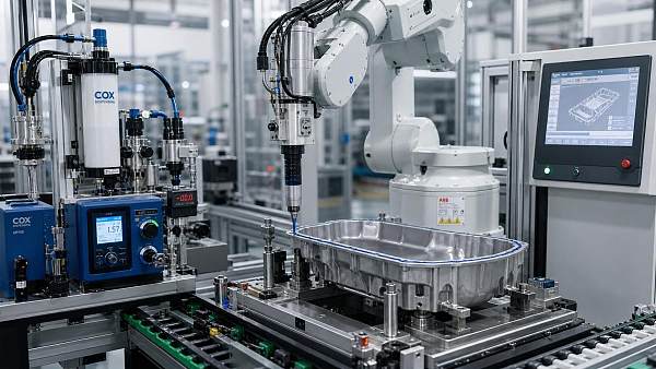
A valve may dispense a consistent flow rate in a stationary test and still produce nonuniform beads on a moving assembly. During acceleration, deceleration, corners, and direction changes, the robot path alters the relationship between deposited material and surface travel. If the valve command does not compensate for motion, material tends to accumulate at starts, stops, and corners while long straight sections may become thin.
This becomes important with sealants applied around rectangular housings, structural adhesives deposited along complex flanges, and thermal interface materials dispensed into patterned cavities. The program should define whether flow is held constant, ramped, interrupted, or synchronized to speed. Corner behavior may require a distinct parameter rather than a global pressure adjustment. Lowering pressure to reduce corner buildup can create underfill on high-speed segments.
Placement accuracy also matters. A correctly dosed bead can fail its intended function when it is offset from the sealing land, bond flange, or encapsulation boundary. Vision guidance, fixture repeatability, part datum control, and robot calibration should be considered separately from volume control, even though their defects may look similar during visual inspection.
Build verification into normal production rather than only setup
Initial setup validation is necessary, but it does not show whether the process remains stable. Material lots, ambient conditions, nozzle wear, and supply changes can shift performance after a program has been approved. A practical control plan identifies a measurement that is sensitive enough to reveal drift before defective assemblies accumulate.
For discrete dots or shots, gravimetric sampling can be appropriate when the sampling method is controlled and the material does not evaporate or react in a way that distorts the measurement. For continuous beads, vision-based width measurement may help identify placement and gross flow changes, while bead height or cross-sectional checks may be needed where sealing performance depends on volume. Pressure and valve-cycle trends can provide useful early-warning signals, but they should be correlated with physical deposits during process qualification.
Trend changes should trigger an investigation, not automatic adjustment of several parameters at once. When pressure, open time, temperature, robot speed, and stand-off are altered together, the root cause becomes difficult to identify. A disciplined response changes one verified variable, records the effect, and confirms that the correction remains valid across the expected operating window.
Practical evaluation points before approving a dispensing system
Technical approval should be based on representative trials. The material, packaging format, target substrate, nozzle type, production speed, and cure-related constraints should resemble the intended process as closely as possible. A short demonstration with a clean valve and freshly prepared material may prove basic feasibility, but it does not establish stable dosing over the conditions that matter in production.
- Confirm the required unit of control: mass, volume, bead geometry, mix ratio, or coverage area.
- Test at the lower and upper ends of expected viscosity and temperature conditions where permitted by the material specification.
- Observe starts, stops, corners, pattern transitions, and restart behavior after planned pauses.
- Assess how the system handles priming, purge, nozzle replacement, cleaning, and material changeover.
- Check whether process data can distinguish supply instability, valve response issues, and motion-related defects.
- For abrasive or filled materials, evaluate wear points and the effect of maintenance intervals on output.
A dispensing system is well matched when its control method addresses the dominant source of variation. A low-viscosity UV adhesive may require clean shutoff and accurate placement more than heavy-duty pumping. A thermally conductive potting compound may require controlled feed, temperature management, and air handling. A two-part structural adhesive may place ratio accuracy and mixer behavior ahead of maximum cycle speed. Treating all fluids as interchangeable leads to unnecessary tuning and unreliable quality decisions.
The most reliable result comes from connecting the dose requirement to the complete fluid path and the actual part motion. Once pressure behavior, material condition, valve response, and verification method are aligned, dispensing becomes a controlled manufacturing operation rather than a sequence of adjustments made after defects appear.
Recommended News
 Oct 03, 2026When disposable static mixers reduce cleanup time in 2K dispensingStatic mixers disposable options can cut 2K dispensing cleanup, reduce changeover risk, and improve uptime. Learn how to balance waste, mixing quality, and cost.
 Sep 27, 2026How fluid control systems dispensing improves dosing consistencyFluid control systems dispensing improves dosing consistency by stabilizing pressure, flow, valve response, and motion—helping manufacturers reduce waste, defects, and rework.
 Sep 21, 2026What drives industrial screw pumps price beyond flow rateIndustrial screw pumps price depends on more than flow rate. Explore how materials, pressure, seals, controls, and lifecycle costs shape the right investment.
 Aug 15, 2026Do inline static mixers improve mixing consistency in dosing lines?Static mixers inline can improve dosing line consistency by reducing streaks and variation, helping you achieve more reliable mixing and better process results.
 Jul 14, 2026Static Mixing Technology: When It Improves DispensingStatic mixing technology improves dispensing by delivering more consistent 2K adhesive mixing, stable cure results, and lower rework. Learn when it adds real value in production.
 Jul 13, 2026Static Mixers for 2K Adhesives: How to Match Mix Quality and FlowStatic mixers 2K adhesives guide: learn how to balance mix quality and flow, reduce waste, control pressure, and choose the right mixer for reliable bonding performance.
 Jul 12, 2026Static Mixers for Epoxy: How to Reduce Waste and Improve Mix QualityStatic mixers epoxy guide: learn how to reduce waste, improve mix quality, prevent cure defects, and choose the right mixer for reliable, cost-efficient epoxy dispensing.
 Jul 10, 2026Dispensing Systems for Sealants: Reducing Waste and Cycle TimeDispensing systems for sealants help cut waste, improve bead accuracy, and shorten cycle time. Learn how the right setup boosts sealing quality, consistency, and production efficiency.
 Jul 05, 2026Static Mixing Systems: When Pressure Loss Becomes a Production ProblemStatic mixing systems can boost blend quality, but too much pressure loss can disrupt flow, ratio control, and throughput. Learn the warning signs and practical fixes.
 Jul 05, 2026How to Compare Screw Pumps for Stable Industrial DispensingScrew pumps industrial comparison made practical: learn how to assess flow stability, repeatability, wear, and integration to choose a dispensing solution that cuts scrap and boosts uptime.
 Jun 28, 2026Industrial Screw Pumps: Cost Factors That Affect Dosing AccuracyIndustrial screw pumps impact far more than upfront cost. Discover how fluid compatibility, wear, calibration, and maintenance affect dosing accuracy, waste, and total ownership cost.
 Jun 22, 2026How to Compare Adhesive Viscosity Control Suppliers for Stable DispensingAdhesive viscosity control supplier comparison guide: learn how to evaluate rheology, batch consistency, equipment fit, and support to achieve stable dispensing and reduce downtime.
 Jun 20, 2026Fluid Dispensing Engineering Basics for Stable Bead Size and OutputFluid dispensing engineering explained for stable bead size and output. Learn key variables, common instability signals, and practical ways to improve accuracy, yield, and process reliability.
 Jun 18, 2026Static Mixing Technology for Polyurethane: What Affects Mixing Quality Most?Static mixing technology for polyurethane: discover what impacts mixing quality most—from ratio accuracy and viscosity to temperature and mixer design—to reduce defects and improve stable output.




Editor's Selection
The Archive Newsletter
Critical industrial intelligence delivered every Tuesday. Peer-reviewed summaries of the week's most impactful logistics and market shifts.