
Capillary Underfill Bonding: Key Process Risks and Control Points
by
Published
Views:
Capillary Underfill Bonding: Key Process Risks and Control Points
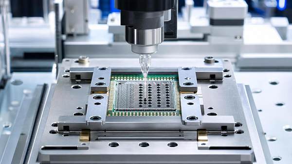
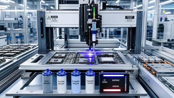
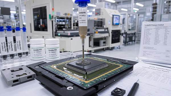
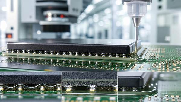
Capillary underfill bonding is often described too loosely. In practice, it does not mean “dispense glue under the package and cure it.” It refers to a tightly coupled assembly step in which a low-viscosity underfill is introduced along the edge of a mounted device, then drawn by capillary action into the gap between the package and the substrate. The purpose is straightforward: redistribute thermo-mechanical stress away from solder joints, reduce fatigue damage during temperature cycling, and stabilize fine-pitch interconnections that would otherwise be vulnerable to cracking, warpage, shock, or moisture-driven failure.
That sounds simple until yield data starts to move in the wrong direction. Technical evaluators usually discover that underfill performance is less about the datasheet headline and more about process interaction: package stand-off, bump pitch, flux residue, substrate topography, dispense pattern, wetting behavior, cure profile, and inspection capability all matter. A material that behaves well in one package family can become a chronic source of voids or incomplete flow in another.
The term is most closely associated with flip chip, CSP, BGA-adjacent reliability strategies, and other advanced electronic packaging environments where the gap is small and the interconnect density is high. In those settings, capillary flow is not just a filling mechanism. It is the process window itself. If the fluid does not advance uniformly, if air cannot escape, or if the material cures with excessive shrinkage stress, the assembly can fail even though dispense volume and cure time appear to be “within spec.”
Where the Real Risk Begins
A common misunderstanding is to treat underfill as a secondary protection layer added after electrical assembly is complete. In reliability terms, it becomes part of the package structure. Once cured, it changes stress distribution, moisture pathways, rework difficulty, and sometimes downstream inspection limits. That is why capillary underfill bonding should be evaluated like an integrated package-process-material system, not like a generic sealing step.
The first control point is gap fill behavior. Capillary flow depends on the balance between surface energy, viscosity, temperature, and geometry. Narrow gaps can improve capillary driving force, but they also increase sensitivity to contamination and flow obstruction. If flux residues, solder mask irregularities, corner fillet geometry, or particles disturb the flow front, the result may be trapped voids or dry zones beneath the die. Those defects are especially hard to accept because the external fillet can still look normal.
Incomplete flow is not always caused by a “bad material.” Sometimes the dispense path is too short for air evacuation. Sometimes board temperature is drifting. Sometimes a package has more warpage than the process was qualified for. In miniature assemblies, even small changes in stand-off height can alter fill time and void tendency enough to push the line outside a stable window.

The second control point is cleanliness. Underfill materials are expected to wet metallization-adjacent surfaces and flow through very small spaces. That makes them unusually sensitive to ionic contamination, unremoved flux residues, surface treatment variability, and handling-related contamination such as fingerprints or airborne particles. “No-clean” does not automatically mean “underfill-compatible.” In many electronics lines, this is one of the more expensive lessons because the residue may not create an immediate electrical defect, yet it can still distort flow, reduce adhesion at critical interfaces, or contribute to long-term reliability loss during humidity or thermal cycling.
Why Voids Matter More Than Their Size Suggests
Voids are often discussed as a cosmetic issue until someone correlates them with field returns. Their significance depends on location, not only volume fraction. A small void near a high-stress corner, a solder bump cluster, or a crack initiation zone can be more problematic than a larger void in a less stressed region. In capillary underfill bonding, voids usually come from air entrapment, outgassing, moisture, poor wetting, interrupted flow fronts, or excessive viscosity during filling.
This is why simple pass/fail language around “void-free fill” can be misleading. The practical question is whether the process can repeatedly produce an acceptably low and well-characterized void profile under actual production conditions. That usually requires more than microscope checks at the fillet. Depending on package type and reliability requirements, X-ray or cross-section analysis may be necessary during process qualification, especially when new substrate finishes, flux chemistries, or package geometries are introduced.
Another trap is assuming that lowering viscosity always improves flow and reduces voids. Lower viscosity can help filling, but it may also change bleed behavior, filler stability, fillet control, or material migration during preheat. The right viscosity range is package-specific and process-specific. Technical evaluation should therefore look at rheology over the actual dispense and fill temperature range, not only at a single nominal test condition.
Cure Is Not Just the End of the Process
Many line teams focus heavily on filling and treat curing as a separate oven-setting task. That separation is convenient, but technically incomplete. Cure schedule influences residual stress, adhesion development, coefficient-of-thermal-expansion mismatch response, and sometimes void evolution. A fast cure may support throughput, yet it can also lock in shrinkage stress too aggressively or amplify package warpage effects. A slower cure may be more forgiving mechanically, but it can create takt-time pressure or require tighter material latency control upstream.
For that reason, cure optimization should be linked to package reliability targets, not chosen purely from supplier baseline recommendations. In advanced assembly, the best curing profile is often the one that achieves sufficient conversion and adhesion while keeping stress manageable across the specific die size, substrate design, and thermal exposure profile of the application.
There is also a procurement implication here. Two underfills may appear comparable on broad descriptors such as epoxy chemistry, capillary flow, or cure temperature range, yet behave very differently once actual cure shrinkage, filler content, modulus development, and warpage response are considered. For technical evaluators, this is where supplier comparison needs to move beyond the front-page datasheet.
Control Points That Usually Deserve Qualification Attention
None of these points are exotic. The difficulty is that small weaknesses can reinforce each other. A slightly contaminated surface, a marginally higher viscosity lot, and a modest package warpage shift may individually seem tolerable, but together they create a repeatable void pattern. That is why robust control plans usually rely on interaction thinking rather than one-variable troubleshooting.
Material Selection Is Really a Process Fit Decision
When people ask for the “best” underfill, they often mean the one with the strongest reliability reputation. That is not a sufficient selection logic. Capillary underfill bonding materials need to be screened against actual package architecture, assembly temperature limits, line takt time, rework policy, inspection method, and expected service environment. A high-modulus material may improve some fatigue outcomes while increasing stress elsewhere. A lower-temperature cure may help temperature-sensitive components while complicating throughput or conversion completeness. A filler system that improves thermo-mechanical properties may make flow harder in ultra-narrow gaps.
For technical evaluation, the practical questions are usually better than generic performance claims:
- Can the material fully wick under the target package within a stable and production-ready time window?
- How sensitive is the fill result to normal variation in board temperature and package stand-off?
- Does the cure profile create unacceptable warpage or residual stress?
- Is the material compatible with the existing flux and cleaning strategy?
- Can defects be detected with the inspection tools already available on the line?
- Does the reliability test plan reflect the actual field stress profile rather than a generic benchmark?
That set of questions usually reveals more than broad sales language around “high reliability” or “excellent capillary flow.”
Standards, Evidence, and What Should Be Verified
There is no single shortcut standard that answers every underfill decision. In real qualification work, teams often combine internal process acceptance criteria with package reliability testing, materials compatibility checks, and broader electronics manufacturing standards such as IPC-related workmanship or assembly guidance where relevant. The exact standard set depends on product type and sector. Automotive, industrial control, consumer electronics, and high-reliability electronics do not always judge risk the same way.
What matters is disciplined evidence. If a supplier claims compatibility with fine-pitch assembly, the evaluator should ask under what gap range, cure condition, and substrate condition that statement was established. If a process team reports low defect rates, the question is how those defects were detected and whether the sample set included worst-case package geometry. If reworkability is important, that needs direct confirmation because many capillary underfills are chosen for permanence, not easy reversibility.
The same caution applies to compliance language. Requirements such as RoHS, halogen-related restrictions, or customer-specific material declarations can be relevant to underfill selection, but they do not predict assembly success. A compliant material can still be a poor process fit.
What Experienced Evaluators Usually Look For
Experienced teams tend to read capillary underfill bonding through three lenses at once. The first is manufacturability: can the line run it consistently without hidden defect formation? The second is reliability: does it reduce solder joint risk under the actual thermal and mechanical load profile of the product? The third is control burden: how much monitoring, material conditioning, and inspection discipline is required to keep the process stable?
That last point is often underestimated. Some materials produce excellent results, but only under narrow thermal and cleanliness conditions. Others may offer a broader process window with slightly less aggressive mechanical performance. There is no universal winner. The right choice depends on where the product can tolerate variation and where it cannot.
A sound evaluation of capillary underfill bonding therefore starts with the flow path, not the brochure; with contamination control, not only cure temperature; and with defect detectability, not just nominal material properties. Once those are understood, the term stops being a vague packaging phrase and becomes what it should be: a reliability-critical assembly discipline that lives or fails on process control.
Recommended News
 Aug 19, 2026What affects yield most in the screen bezel bonding processScreen bezel bonding process yield depends most on surface cleanliness, dispensing consistency, alignment, and cure control. Learn how to reduce defects and improve bonding reliability.
 Aug 14, 2026Display Bonding for LCD: How to Reduce Optical Mura and Air Gap RiskDisplay bonding for LCD explained: reduce optical mura, eliminate air gaps, and improve bonding clarity with practical process tips.
 Aug 08, 2026How to Evaluate a Display Bonding Materials Supplier for Optical Clarity and YieldDisplay bonding materials supplier evaluation starts with optical clarity and yield. Learn how to compare process support, reliability, cure control, and production fit.
 Jul 30, 2026How to Evaluate Conductive Electronic Adhesives for Fine-Pitch BondingConductive electronic adhesives for fine-pitch bonding demand more than high conductivity. Learn how to assess rheology, cure, adhesion, and stability to reduce shorts and improve yield.
 Jul 25, 2026Capillary Underfill Bonding: Key Process Risks and Control PointsCapillary underfill bonding explained: discover key process risks, void causes, cure challenges, and control points to improve assembly yield, reliability, and package performance.
 Jul 21, 2026Industrial Adhesive Market Trends in Electronics for 2026Industrial adhesive market trends electronics in 2026 reveal how faster curing, precision dispensing, and compliance shape reliability, cost, and smart sourcing in electronics manufacturing.
 Jul 10, 2026Display Bonding: Key Failure Modes and Material Trade-OffsDisplay bonding failure modes explained: compare OCA, LOCA, and material trade-offs affecting optics, durability, yield, and process control across demanding display applications.
![]() Jul 07, 2026Camera Module Sensor Bonding: Choosing Adhesives for Low Stress and Clean OpticsCamera module sensor bonding guide: learn how to choose low-stress, low-outgassing adhesives for clean optics, higher yield, and more reliable camera module assembly.
Jul 07, 2026Camera Module Sensor Bonding: Choosing Adhesives for Low Stress and Clean OpticsCamera module sensor bonding guide: learn how to choose low-stress, low-outgassing adhesives for clean optics, higher yield, and more reliable camera module assembly. Jul 06, 2026Screen Bezel Bonding Adhesive: Key Checks for Strength and Display FinishScreen bezel bonding adhesive selection starts with more than strength. Learn the key checks for gap control, curing consistency, aging durability, and cleaner display finish.
 Jul 05, 2026Underfill Material Manufacturer Checklist for Consistent Bond ReliabilityUnderfill material manufacturer checklist for stronger bond reliability: compare flow stability, quality control, compliance, and supply support to reduce defects and choose with confidence.
 Jul 03, 2026Consumer Electronics Bonding Supplier Checklist: Quality, Lead Time, and Process FitConsumer electronics bonding supplier selection starts with quality, lead time, and process fit. Discover a practical checklist to reduce risk, improve yield, and choose with confidence.
 Jun 29, 2026Camera Module Bonding: How to Reduce Shift and FoggingCamera module bonding guide to reduce shift and fogging with better adhesive selection, dispensing, and curing control. Learn practical steps to improve yield and optical stability.
 Jun 26, 2026Solder Replacement Adhesives for SMT: Process Limits, Reliability, and ROISolder replacement adhesives for SMT: explore process limits, reliability, and ROI to see where low-heat bonding can cut defects, protect sensitive assemblies, and justify targeted adoption.
 Jun 26, 2026Display Bonding Adhesive Material Selection: Optical Clarity vs. Rework RiskDisplay bonding adhesive material selection shapes clarity, yield, and rework cost. Explore how to balance optical performance with repair risk for smarter, higher-value display assemblies.
 Jun 25, 2026Vietnam Adhesives Show to Spotlight ACA/ACF, UV Line FitVietnam Adhesives Show will spotlight ACA/ACF and UV line fit at VIASEAL Vietnam 2026, revealing localized electronics assembly solutions, certification readiness, and Southeast Asia sourcing opportunities.
 Jun 24, 2026Vietnam Adhesives Show Opens Aug. 5 With ACA/ACF FocusVietnam Adhesives Show opens Aug. 5 in Hanoi, spotlighting ACA/ACF, UV camera module adhesives, and RoHS 3 plus TCVN 7837:2025 compliance for EMS buyers and suppliers.
 Jun 23, 2026Vietnam Adhesives Expo Highlights ACA/ACF and UV Curing ShiftVietnam Adhesives Expo spotlights ACA/ACF conductive adhesives and 365 nm UV curing trends, revealing how Vietnam electronics supply chains are redefining qualification, certification, and sourcing opportunities.
 Jun 21, 2026IEC 62776:2026 Tightens LED Adhesive TestingIEC 62776:2026 tightens LED adhesive testing with mandatory halogen, ion migration, and silver migration checks. See how ACA/ACF and UV-curable adhesive suppliers can stay export-ready.
 Jun 18, 2026Display Bonding Adhesives: Key Checks Before Final Material SelectionDisplay bonding adhesives: discover the key checks before final material selection, from optical stability and curing to dispensing, reliability, and supplier readiness.
 Jun 15, 2026How to Evaluate a Camera Module VCM Bonding SupplierCamera module VCM bonding supplier selection affects yield, focus stability, and contamination control. Learn the key technical and sourcing checks before you shortlist.
 Jun 14, 2026Silver Filled Solder Replacement Adhesives: When Lower Heat Improves Assembly YieldSilver filled solder replacement adhesives help reduce heat stress, warpage, and yield loss in sensitive assemblies. Learn where they outperform solder and how to qualify them with confidence.
 Jun 13, 2026BGA Underfill for Flip Chip: Common Voiding Causes and FixesBGA underfill for flip chip: learn the most common voiding causes, from trapped air to cure issues, and discover practical fixes to improve yield, reliability, and process stability.
 Jun 11, 2026Shenzhen Adhesive Project Signals Supply and Certification ShiftShenzhen Adhesive Project signals change in supply and certification for UV curing adhesive, ACA/ACF anisotropic conductive adhesive, and thermal potting adhesive—see what it means for sourcing, lead times, and compliance.
 Jun 11, 2026Silver Conductive Adhesive for PCB and Sensor Assembly: Key Specs That MatterSilver conductive adhesive selection starts with the specs that drive real performance. Learn how resistivity, adhesion, cure, viscosity, and thermal stability affect PCB and sensor assembly reliability.








Editor's Selection
The Archive Newsletter
Critical industrial intelligence delivered every Tuesday. Peer-reviewed summaries of the week's most impactful logistics and market shifts.